ESP8266 WiFi Smart Thermostat Powered by ESPHome and Home Assistant
Table Of Contents
Overview⌗
I’ve been planning to replace my Nest thermostat with a local-only option since moving into my house. I’d been thinking I would just use a ZWave or Zigbee option, however I also wanted to install a wall-mounted tablet for Home Assistant and the best place to put it was where the Nest was currently mounted. I started poking around for a “headless” thermostat and settled on the Newgoal 4-Channel Tuya board.
Parts List⌗
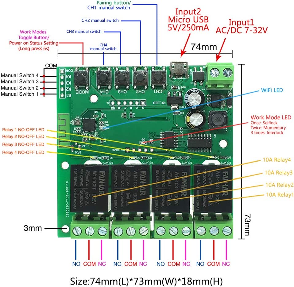
- Newgoal 4-Channel Tuya board
- HiLetgo CP2102 USB 2.0 Serial Converter – This is required to flash ESPHome onto the device over UART. Once flashed with ESPHome, the device can be updated OTA.
- 6 pin male header – In order to connect the CP2102 to the board, we will need to solder a 6 pin header to the board.
- Thermostat wire
Software⌗
- Home Assistant – Used for the temperature sensor and to control the thermostat.
- ESPHome Integration – We will use this to flash/configure the board.
- Tuya MCU ESPHome Component – The board uses a Tuya MCU. We will use this component to configure the 4 relays as Tuya switches.
- Thermostat ESPHome Component – Manages the relays based on the thermostat readings. This is what gets picked up by Home Assistant as a
climateentity. - CP210x Drivers – I use MacOS and used the OSX driver.
Preparing the Board for Flashing⌗
The board does not have a boot button, so flashing over USB didn’t work. In order to flash the board over UART with the CP2102, I had to do a bit of soldering.
Solder the Header Pins⌗
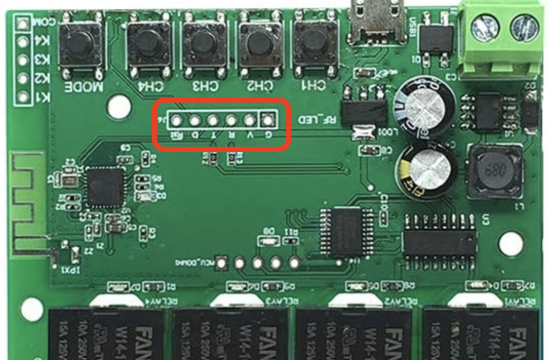
The board has a spot to solder 6 pins into G (Ground), V (Power), R (Rx), T (Tx), D, and RST (Reset). I soldered a 6 pin male header to the outlined spot on the board. We will use these pins to connect the CP2102 USB serial converter to.
Wiring the CP2102⌗
The CP2102 I bought came with a 4 pin wire. This will need to be modified with a jumper from GND that we can use to attach to the D pin on the board.
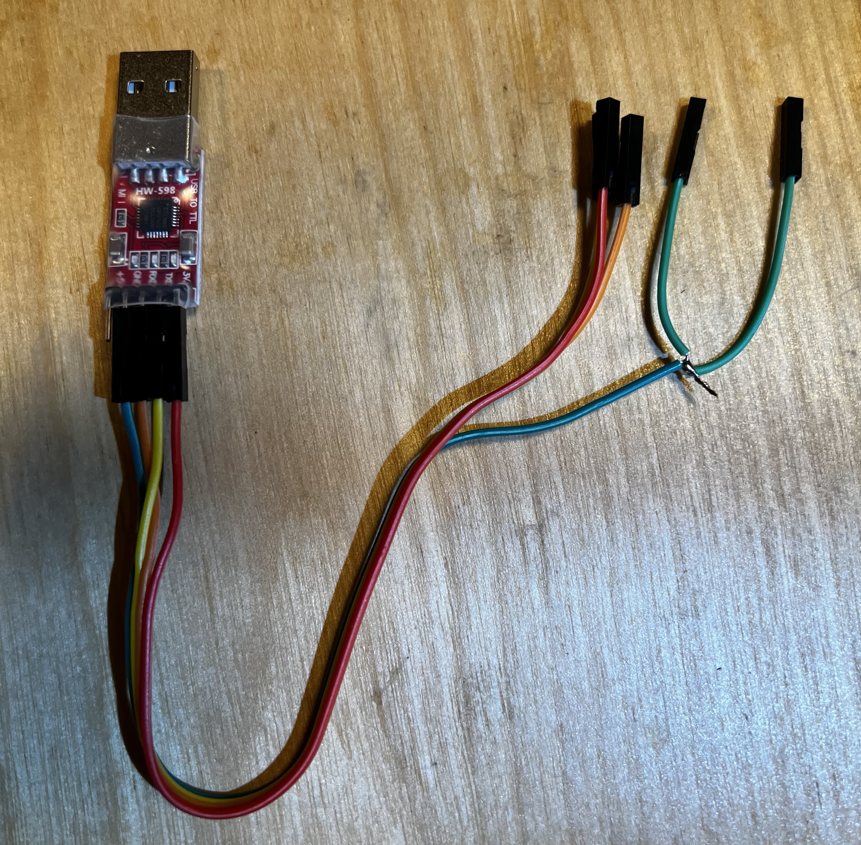
We can now connect the CP2102 to the board with the following pin out:
- CP2102
GND→GandDpins - CP2102
TXD→Rpin - CP2102
RXD→Tpin - CP2102
3V3→Vpin
NOTE: This did not provide me with enough power to flash the device with ESPHome. In addition to the above, I also connected the board to USB power.
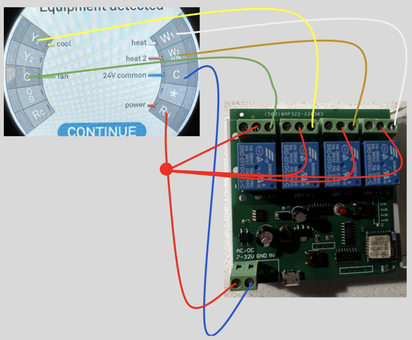
Wiring the Relays to the HVAC System⌗
My HVAC system at home was wired as follows:
Rh– 24V powerB– NeutralY– Air ConditionerG– Fan-onlyW– Heat Stage 1B– Heat Stage 2
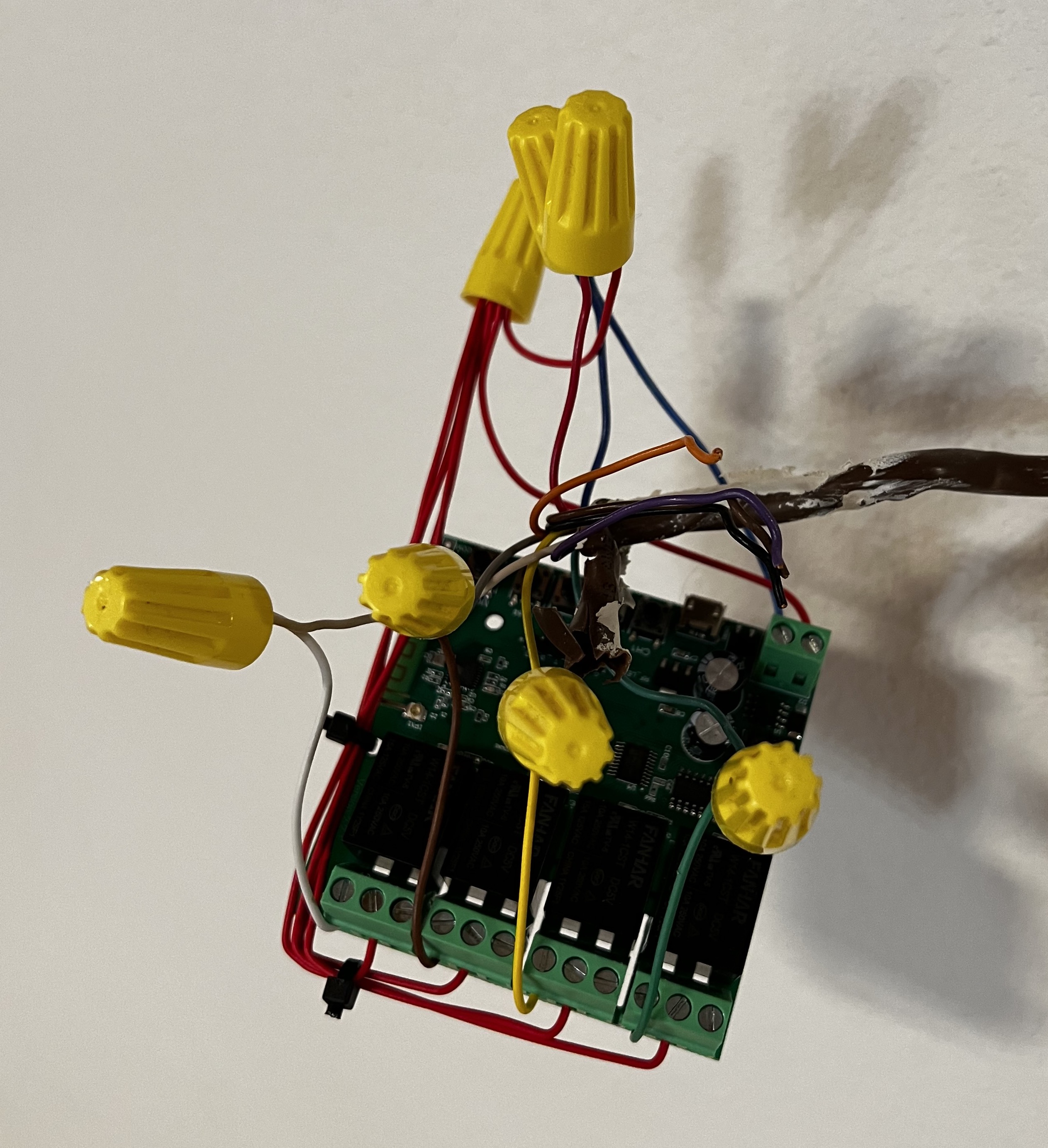
Below is a quick and dirty diagram of what my wiring looks like:
Setting the Hardware Relay Mode⌗
You will want to set the mode to “interlocking”. You can do this by pushing the MODE button until the led flashes 3 times. Interlocking means that only one relay at a time can be open.
Flashing ESPHome⌗
Once you’ve put the solder gun away, it’s time to flash ESPHome. I did this in Home Assistant using the ESPHome integration with Chrome. This worked like all of my other ESP32s except there’s no boot button to press on connect.
ESPHome Configuration for ESP8266 with Tuya MCU⌗
The following is a basic configuration that will expose the Tuya MCU once flashed.
esphome:
  name: living-room-thermostat

# Make sure to use an ESP8266 board.
esp8266:
  board: esp8285

api:
  encryption:
    key: "0GamOcw/LFuS2HYcvVRkj88OUl17WEH/Grf9G3nWdxI="

ota:
  password: "45c182089a39e49022f4316cad690a2f"

wifi:
  ssid: !secret wifi_ssid
  password: !secret wifi_password

captive_portal:

# This MUST be set to 0 in order for the UART bus configured
# below to properly work.
logger:
  baud_rate: 0

# The Tuya MCU communicates over the UART bus.
uart:
  rx_pin: GPIO3
  tx_pin: GPIO1
  baud_rate: 9600

# Register the Tuya MCU connection.
tuya:
Expected Log Output from tuya Component⌗
Once you’ve flashed the board, you can connect to it normally OTA to get the log output. On boot, you should see the Tuya component output some logs that look something like this:
[15:16:28][C][tuya:033]: Tuya:
[15:16:28][C][tuya:048]:   Datapoint 1: switch (value: OFF)
[15:16:28][C][tuya:048]:   Datapoint 2: switch (value: OFF)
[15:16:28][C][tuya:048]:   Datapoint 3: switch (value: OFF)
[15:16:28][C][tuya:048]:   Datapoint 4: switch (value: OFF)
[15:16:28][C][tuya:050]:   Datapoint 7: int value (value: 0)
[15:16:28][C][tuya:050]:   Datapoint 8: int value (value: 0)
[15:16:28][C][tuya:050]:   Datapoint 9: int value (value: 0)
[15:16:28][C][tuya:050]:   Datapoint 10: int value (value: 0)
[15:16:28][C][tuya:048]:   Datapoint 13: switch (value: OFF)
[15:16:28][C][tuya:048]:   Datapoint 101: switch (value: ON)
[15:16:28][C][tuya:054]:   Datapoint 102: enum (value: 2)
[15:16:28][C][tuya:050]:   Datapoint 103: int value (value: 5)
[15:16:28][C][tuya:062]:   GPIO Configuration: status: pin 13, reset: pin 0
[15:16:28][C][tuya:068]:   Product: '{"p":"waq2wj9pjadcg1qc","v":"1.0.0","m":0}'
Configuring ESPHome to Manage the HVAC System⌗
Add a Climate Component to ESPHome⌗
The thermostat climate controller component in ESPHome will require a few things be configured:
- Each relay needs to be exposed as a
switchcomponent. - We need a
sensorthat has adevice_classoftemperature. - A
climatecomponent that calls our relays and consumes our temperature sensor.
NOTE: Because I planned to put this device into a recessed receptacle, and it does not appear to have easily accessible GPIO pins, I decided to use the homeassistant component in ESPHome to consume temperature sensors I already had. I have a bunch of Zigbee and BLE temperature sensors that I expose using ha-average sensor.
# Set up each of our relays.
switch:
- platform: "tuya"
id: fan_only
name: "Fan Only"
switch_datapoint: 1
- platform: "tuya"
id: air_cond
name: "Air Conditioning"
switch_datapoint: 2
- platform: "tuya"
id: heat_stage_2
name: "Heat Stage 2"
switch_datapoint: 3
- platform: "tuya"
id: heat_stage_1
name: "Heat Stage 1"
switch_datapoint: 4
sensor:
- platform: homeassistant
id: current_temperature
# This sensor is an average of multiple sensors throughout
# my house. A mixture of Zigbee and BLE sensors. This will be
# used to drive the thermostat's modes.
entity_id: sensor.upstairs_home_temperature
device_class: temperature
state_class: measurement
filters:
# The sensor I consume from HASS is in F. This converts
# it back to C so it works correctly with the climate component.
- lambda: return (x - 32) * (5.0/9.0);
# Dual-point configuration entry. This consumes the sensor above
# and uses it to control the relay switches.
climate:
- platform: thermostat
name: "Living Room Thermostat"
sensor: current_temperature
default_preset: home
supplemental_heating_delta: 3 °C
startup_delay: True
min_fanning_run_time: 300s
min_cooling_off_time: 300s
min_cooling_run_time: 300s
min_heating_off_time: 300s
min_heating_run_time: 300s
max_heating_run_time: 1800s
min_idle_time: 300s
min_fanning_off_time: 1800s
cool_action:
- switch.turn_on: air_cond
heat_action:
- switch.turn_on: heat_stage_1
supplemental_heating_action:
- switch.turn_on: heat_stage_2
fan_only_action:
- switch.turn_on: fan_only
idle_action:
- switch.turn_off: air_cond
- switch.turn_off: heat_stage_1
- switch.turn_off: heat_stage_2
preset:
- name: home
default_target_temperature_low: 19 °C
default_target_temperature_high: 22 °C
mode: heat_cool
- name: away
default_target_temperature_low: 10 °C
default_target_temperature_high: 30 °C
mode: heat_cool
- name: sleep
default_target_temperature_low: 18 °C
default_target_temperature_high: 24 °C
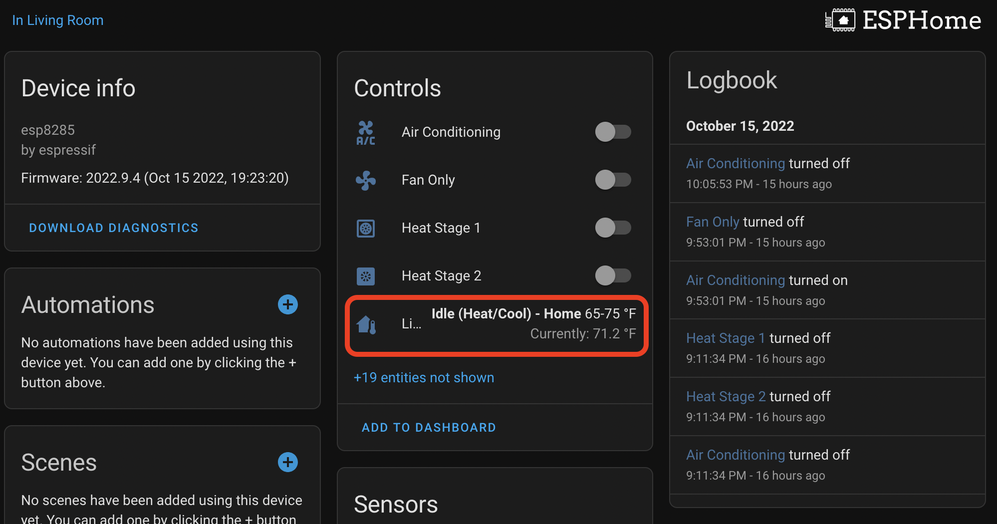
mode: heat_coolAdd Device to ESPHome Integration in Home Assistant⌗
Go to Settings → Devices & Services → ESPHome → living-room-thermostat → 1 device and you should see the following:
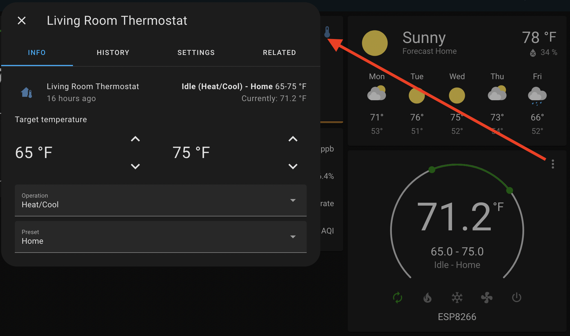
Add Device to Lovelace in Home Assistant⌗
Add the following YAML to one of your dashboards:
# Add this to a list of cards
- type: thermostat
  entity: climate.living_room_thermostat
  name: ESP8266
And you’ll get a nice climate control widget:
Working Proof of Concept⌗
My ESP8266 is currently operating as the climate control for my house. The wiring is rough at the moment. I will be following up with a post about the final product, which will house this, a controlled outlet, and a wall mounted 10.5" Samsung Tab A8.